Article Sources:
- BLRS (Purdue SIGBots)
- https://en.wikipedia.org/wiki/Force
- https://www.sciencing.com/pressure-physics-definition-units-formula-examples-13723383/
Force/Pressure
A force is an influence that can cause an object to change its velocity unless counterbalanced by other forces. The concept of force makes the everyday notion of pushing or pulling mathematically precise. Because the magnitude and direction of a force are both important, force is a vector quantity. The SI unit of force is the newton (N), and force is often represented by the symbol F.
The formula for force can be shown as such:
OR
Force has many units - for ANSI (AKA the US standard) it is denoted as lbs or lbf (short for pound force)
Pressure is simply defined as the amount of force per unit area. The key point when you're trying to understand pressure is to think about what happens on the atomic level in a liquid or gas at high pressure. The constituent molecules are constantly moving around, and this means they're bumping into the walls of the container all the time. The more they move (due to higher temperatures), the more they bump into the walls of the container and the higher the pressure.
The formula for pressure can be shown as such:
Similarly to force, pressure has many units - for ANSI (AKA the US standard) it is denoted as psi.
One of the main things that utilizes pressure in VEX is pnumatics. Pressure from your reservoir tank is the driving action within pnumatics that results in an output force - and this is important to know because it helps you to spec out how many pistons you may need to lift something.
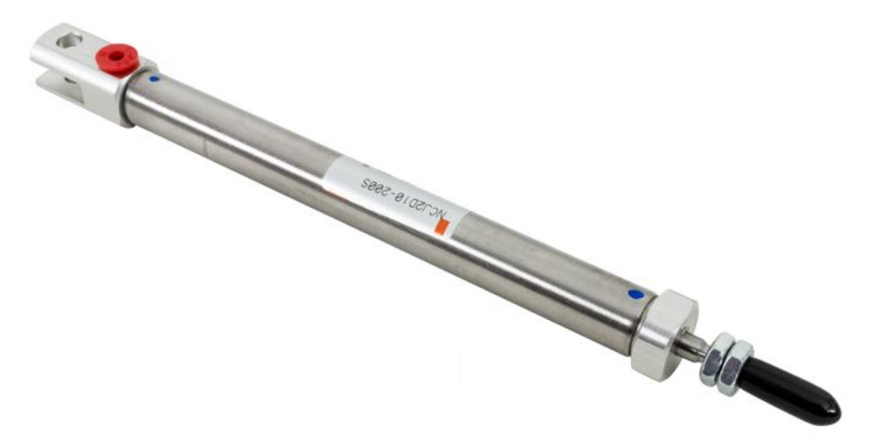
An example below is provided to illustrate how you would calculate the force exerted from your cylinder at a specific tank pressure:
---x---x---x---x---x---x---
(Standard Competition Pressure)
(Cylinder Bore Diameter)
(Cylinder Bore Diameter)
---x---x---x---x---x---x---
Torque
Torque, also known as moment of force, is a measure of the rotational force applied to an object. It is defined as the product of the force applied to an object and the distance from the object's axis of rotation to the point where the force is applied. Torque is a vector quantity, meaning it has both magnitude and direction.
Torque is often represented by the symbol "τ" (tau) and is calculated by the following equation
where:
τ(tau) is the torque, measured in newton meters (N·m)Fis the force applied to the object, measured in newtons (N)dis the distance from the axis of rotation to the point where the force is applied, measured in meters (m)
Torque is an important concept in mechanics, as it is used to measure the ability of an object to rotate around an axis. It is a fundamental principle in the operation of machines, such as motors, gears, and levers, which use torque to transmit power and motion.
In robotics, the most common way that torque is important is anything relating to motors. In a drive train, torque is needed to accelerate quickly, hold a top speed, and be able to push opponents on the field. In a lift, more torque allows the ability to lift heavier loads, lift items faster, and maintain speeds during lifting. For a flywheel, torque allows for higher speed, less loss of speed between shots, and easier tuning of speeds.
In summary, torque is a measure of rotational force that is essential in the design and operation of machines and structures. It is used to calculate the ability of an object to rotate, transmit power, and withstand external forces.
RPM
RPM, or revolutions per minute, is a measure of the rotational speed of an object. It is defined as the number of complete revolutions an object makes around its axis of rotation in one minute. RPM is often used to describe the speed of mechanical systems, such as motors, gears, and shafts.
The relationship between RPM, torque, and the speed of a shaft is complex and depends on several factors, including the size and shape of the shaft, the type and amount of load being applied, and the efficiency of the system.
In general, the torque required to rotate a shaft increases with the speed of the shaft. This is because the faster an object rotates, the more force is required to overcome the centrifugal forces acting on it. As a result, shafts operating at high speeds typically require higher torque to maintain their rotational motion.
Conversely, the speed of a shaft is directly proportional to the torque applied to it, assuming the load and efficiency of the system remain constant. This means that increasing the torque applied to a shaft will result in an increase in its speed, and decreasing the torque will result in a decrease in its speed.
The RPM and torque of a shaft are important factors to consider in the design and operation of mechanical systems. Engineers must carefully balance these variables to ensure that the system operates efficiently and safely and that the shaft is able to withstand the forces acting on it.
For physics analysis, it's best to convert from RPM to radians per second:
Gear Ratios
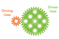
A Gear Ratio is defined as the ratio of the rotational speeds of the first and final gears in a train of gears or of any two meshing gears. Essentially, the ratio of the input speed to the output speed of a geared set of shafts. These can be decided to choose a ratio of Speed (large gear driving small gear) or Torque (small gear driving large gear).
Gear ratios are often simplified fractions of the number of teeth on each gear. This is because (at least in Vex) gears have a proportional number of teeth to their diameter which defines the difference in output speed. From the above image, there is a 12 tooth gear, driving a 36 tooth gear which would constitute a 3:1 ratio.
The benefit of gear ratios is the ability to choose speed vs torque in a system. These have an inverse relationship however where a faster output will have lower torque. With the above example, the output shaft has 3x the torque, but also 1/3 the speed.
Center of Mass (COM)
The center of mass significantly impacts the robot's maneuverability. Make sure to consider its effect on each subsystem during the design stage, rather than addressing it after the robot is built.
The center of mass (COM) or center of gravity (COG) of a robot is the mean location of all the mass of a robot.
Measuring COM Position
- Model the robot in CAD, and use a "measure"-type tool.
- Lift the robot by the chassis using 2 fingers. When the robot balances on your fingers, the XY location of the COM will lie in the line formed by your 2 fingers.
- Hang the robot, and observe how the robot tilts to settle.
Vertical COM Position (Z)
When a robot brakes, the friction between the wheels and the floor rapidly decelerates the robot (velocity is in the opposite direction of acceleration in this case). This creates a torque around the center of mass of the robot, jerking the back of the robot up. In many cases, the rear wheels lose grip with floor as well.
To mitigate jerking ...
- lower the height of the COM off the ground
- use lighter materials in the upper sections of the robot (ex. 1x1 L channels on arms, plastic screws / nuts)
- use heavier materials in the lower sections of the robot
- decrease the max acceleration available to the driver
- implement motion profiling and other motor control techniques
Horizontal COM Position (XY)
Turning
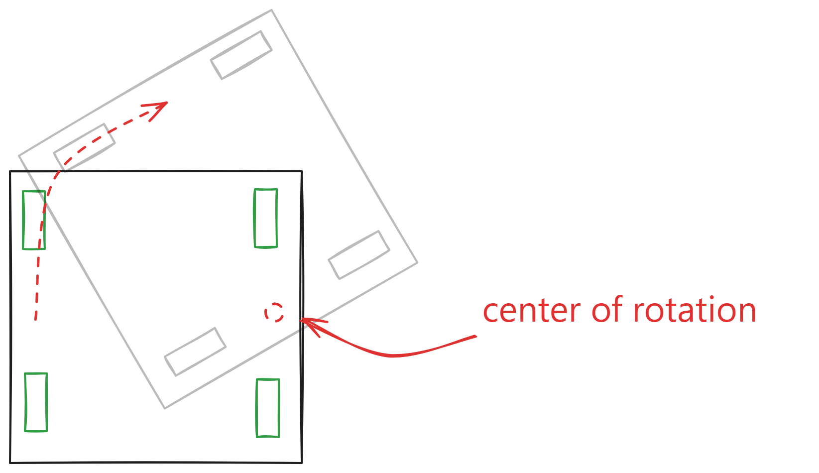
The turning center of the robot is less predictable if the COM (in the horizontal plane) is far from the midpoint of all the wheels. Keeping the COM centered side-to-side and front-to-back ensures more stable and predictable turning.
Hanging
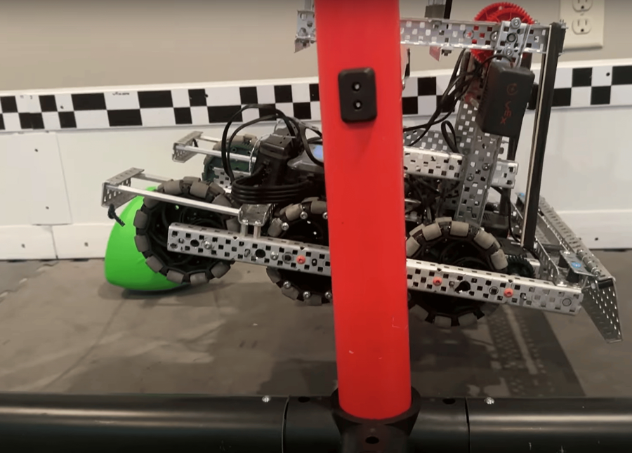
The end effector used during a hang is typically implemented with a joint. If the horizontal COM is offset from the point where the robot hangs, the robot will tilt until the COM aligns directly beneath the hanging point.
Control
To control the position of the COM in the XY plane ...
- place towers optimally after building the chassis
- add/remove weight selectively around the robot